Sunday, May 30, 2010

101a


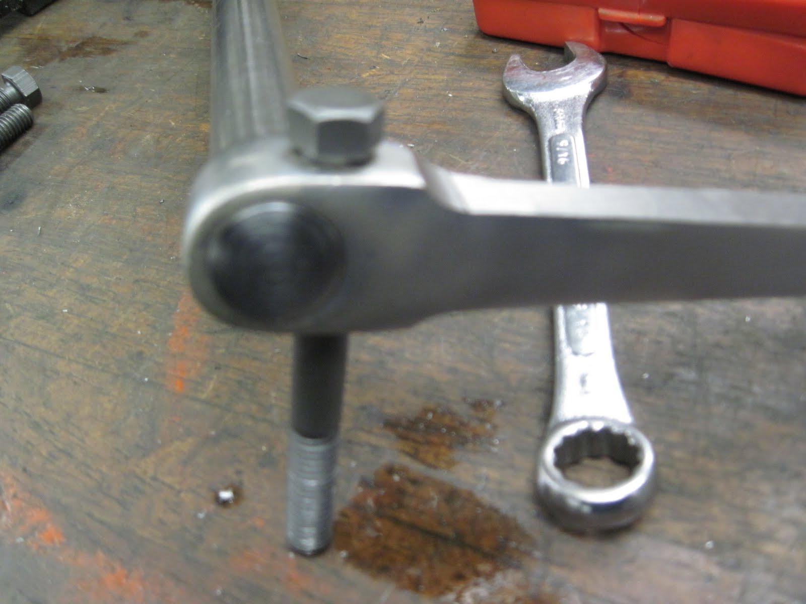
I was pretty excited when I found these pedal arms . They are forged steel and look a lot like stock sears pedal arms except a lot beefier. I figured that all I had to do was some light grinding and radiusing and they would be fine..... wrong! It took me all day to widdle these things into looking right. The first thing that had to be done was to bore the hole out .140 to fit on the stock .750 pedal shaft.


The o.g. sears arms taper down to .450 on the pedal end. This was pretty easy to do. I raised the end up with the plainer jack to cut the correct taper.


Here is a side by side comparison, the one on the bottom is cut and the top one is the bulky version.


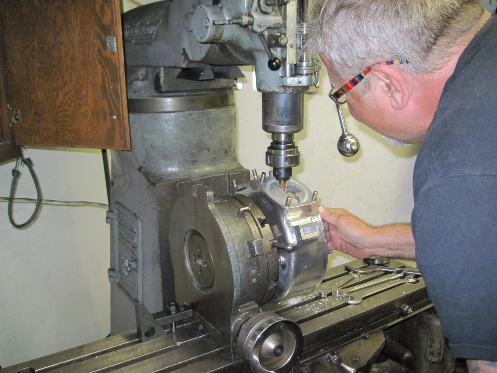
The next step was to cut the .625 radius into the big end. Then I cut over all taper into them. I left a little bit of material on the end for hand grinding.


The next step was to cut the radius on the backside face of the arm on the big end. This was done on the mill, then hand ground in. Finally I was able to radius and grind the small end of the arm. I left it a little bigger than stock just for strength. These were a lot of work, but I am very happy with how they turned out and I would do it again.

101c


Check out the radiused end and the nice fit on the pinch bolt!


Here is the finished piece. I still have to make the actual bolts and silver solder the starting disc onto the pedal shaft, but for the most part it is finished!

Saturday, May 29, 2010

post number 100


I spent the day making my first centerstand. There are a lot of processes involved in this piece. For starters, you can't get channel iron that has the correct dimensions, so you have to make it. I found some rectangular bar stock that was close to what i needed and milled out the center. This piece is over four feet long, so I had to do it in three set ups. After dialing the piece into the head within .002 I hogged out the center of the stock to a depth of .300. Then I cut a chamfer on each side with this 60 degree cutter.


Here is the fixture that I made for bending it up.


The trick is to pull the metal while you are bending it. The outside slugs were not installed in the first step.


Here it is after the second bends on each side.


Here are the ends welded on. I made a fixture to hold these in place too. This project would go a lot faster if I didn't have to make a fixture for every thing haha.

Friday, May 28, 2010

post number 99


Yesterday my friend Sonal drilled out all of my muffler castings. I didn't get a picture of her doing it, so this pic will have to work. Here she is with my daddy.


I found this piece of scratch paper from when my dad and I were figuring out my front struts and fork dampeners. This is a good example of our blueprint skills.
Here is some raw material that i got today. guess what I plan on making out of this stuff.


Here is some more neat stuff that came in the mail. a chunk of 8620 steel for my pedal shaft, some 4130 .75 hex and tool box doors. Lots of fun stuff, this will keep me busy all weekend.


Thursday, May 27, 2010

post number 98


Well I spent six hours on tracking down this bearing today. What a rollercoaster of talking to people all over the world to get the bearing that I need. I was ready to say "uncle" and just have a small batch of the made up, but I lucked out and found one that is dimensionally the same on the i.d. and o.d. but has 2 more balls than stock. This is great news and my phone time paid off, woo hoo

I spent the rest of the day working on drilling out my rear fender for braces, mounting holes and the chain cut out. I borrowed an original fender from a friend and have to send it back tomorrow, so I made use of copying all of the details that I could.


Check out the round headed screws and square nuts that hold the braces on. What a neat detail. The screws and nuts are painted red. I think that Bill Nugent's sears has the same feature


Here are the notes that I took for the fender lay out. There was a third hole in the back of the fender that was kind of strange. I think it may have been for a olsol light. I am not sure though. anyways it is pretty obvious that I am not good at drawing by looking at this pic lol. Check out the striping details in the lower right hand corner. Lots of good details on this sheet of paper!

Wednesday, May 26, 2010


I spent the morning straightening frames. While I was gone Delmar flew down with his wife and Gerald and delivered some clutch parts for the sears project. They are soooo beautiful! Thanks Delmar you do great work.


I also got some muffler castings in the mail. The minimum order at the foundry was 10 pieces, so I guess I will have these for the rest of my life lol.


Here are the outer lock nuts. I have to make up a die to crimp the counter bore down and hold the washer in place.


The tape measure is at the top of the threads in this picture.


and to the center of the axle it measures 27.5 inches.

Tuesday, May 25, 2010

Monday, May 24, 2010

2010 sears picture


Here is a pic of my sears so far. What do you guys think? The project is coming along!!! woo hoo, I Just need a frame now. Should be kind of rolling next week if everything goes well. Wish me luck and have a nice night

post number 95


I spent the day working on shop bikes which is bittersweet. It is difficult to not work on my sears with the weight of this luminous deadline hanging over my shoulders, but at the same time it is great to be able to make some money and work on knuckleheads! After hours I spent an hour ordering material for my center stand various bolts and trying to find this damn bearing. It has proved to be very difficult. I have three different companies looking for me, bu I may end up having to make the thing from scratch. I have a game plan/vision of how to do it in my head, but hopefully I will be able to avoid the process and the money it would cost in tooling...


This is a piece of hail that fell out of the sky today. it is an inch in diameter! These made a big noise when they hit our metal building shop!


Here is my first clutch gate. My friend Sonal came out and prepped all of the pieces and cut the rivets to the correct length. I peened these over. I still have to sand them down so that the edge is nice and smooth. It is a nice piece. Thanks sonal!

post number 94


Well today started out good, I got my fenders from Ohio. The tooling was pretty costly, so I had some extra blanks made up. They are made out of a little heavier gauge of metal which is a huge advantage on the rear fender since it is the muffler/toolbox mount!


The rear fender is pretty long and needed to have an extra piece welded onto the end to make it the correct length. pat even cut the tips of the fender so that it would be less work for me. Thanks man. These are soooo nice!

Sunday, May 23, 2010

post number 93


I have been waiting for a long time to do this shot! WOOO HOOO! Still a lot of work to do, in a couple months, but there is a light at the end of the tunnel.


Here is the front rocker stud. I will be using a friction dampner similar to jd racers. This seems like a good theory and hopefully will be worth the effort.


HEre are the rocker studs for my front end. I made them today. They are made out of 8620 steel and will be case hardened and finished ground!

post number 92

I just had an intense day of working on my sears struts. These are the bars that go from the rockers to the leaf spring on the fork. I don't feel like typing out explanations so The pics will have to do tonight. I have to wake up in six hours and go circuit train. wish me luck and have a great day.


'
They still have to be welded, but you get the idea. Pretty neat stuff!


post number 91


Yesterday my daddy and I worked all day together on my sears. It was my birthday, and it was a perfect day. We kicked ass and put out a lot of fires and made progress! When we made our flywheels, we increased the stroke by .23 in order to have clearance for the crank pin nut and at the same time use the same length rod with different piston pin height. Consequently we had to relieve the cases a bit to make room for the connecting rods. Here is a pic of my daddy milling some relief in the cases.


Once we got the grooves notched out we had to mill out the baffle plates.


Here is what it looks like after some machining. There is at least .060 clearance betwen the bottom of the piston and the case.


Here is a pic that tim took of us checking it all out. What a fun project.


Check it out! A stroker sears!

Friday, May 21, 2010

post number 90


I got some parts from my friend Ron today. Here are the toolboxes. They have to be individually fit and soldered together, but this sure beats making them from scratch.


Here are some clutch parts. They turned out well. OG clutches are steel on steel, I am having the female plates lined with kevlar. The spring plate is a machined solid piece rather than two pieces brazed together. The clutch guide is very nice, I sent Tim into aberdeen to pick up some sickle rivets for it. I am making good progress on my fork and will have some more pics later on today!

Thursday, May 20, 2010

post number 89


Well my rockers are coming along nicely. This whole process has been a real challenge but at the same time a lot of fun. Designing parts is a blast! In this picture Iam boring a 1.75 hole into the rocker for the axle block to fit into. I did both rockers in the same set up, although I had to offset the rocker spacing accordingly.


Here is the other side. This is an interrupted cut, so it was kind of a pain and slow going.


Here is the latest picture of them. My next step is to make some rocker studs and then figure out the necessary spacing for welding the axle blocks into place. Holy moly what a bunch of work.